
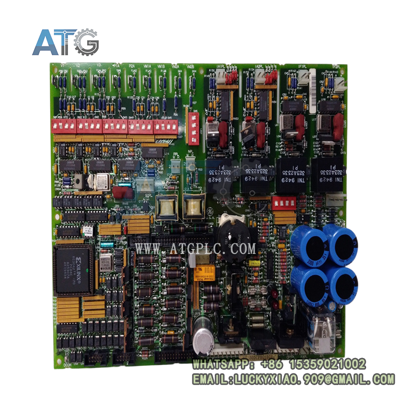
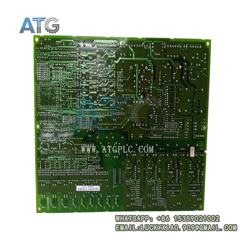

Description
GE DS200DCFBG1BGB Product Description
Product Overview
The GE DS200DCFBG1BGB is a DC power supply and feedback board from the DS200 product line, built for GE Speedtronic Mark V turbine control systems and EX2000 excitation platforms. It serves a dual critical role within drive and excitation cabinets: it generates regulated low-voltage DC rails for control electronics, and it processes high-voltage and current feedback signals for closed-loop regulation.
This board accepts AC input from the control power transformer, converts it into multiple isolated DC outputs, and distributes power to logic circuits, monitoring modules and enclosure fans. On the feedback side, it uses voltage-controlled oscillator (VCO) technology to convert analog voltage and shunt current signals into proportional frequency outputs, which are then sent to the main drive controller for precise closed-loop control. Designed for harsh power electronics environments, it delivers stable power delivery and accurate signal conditioning for medium-voltage drive and static excitation applications.
Core Product Features
- Generates three regulated DC output rails — +5 V, ±15 V and ±24 V — to supply logic circuits, analog signal processing and field interface devices from a single board.
- Integrated VCO feedback circuits convert millivolt-level shunt current and bridge voltage signals into 0–500 kHz frequency outputs, eliminating noise interference on long signal paths.
- Three on-board fuses protect each power rail independently, preventing cascading damage in the event of a short circuit on one output.
- Five dedicated test points plus multiple diagnostic access points allow technicians to verify rail voltages and feedback signals without removing the board from the rack.
- Seven DIP switch banks and 12–13 jumper pins support configurable voltage scaling, feedback gain and operating mode settings for different drive and excitation configurations.
- Front-panel LED and neon indicators provide at-a-glance status for fuse health, power presence and fault conditions.
- Natively compatible with EX2000, DC2000, AC2000, FC2000, CB2000 and ME2000 series drive and excitation systems for broad deployment flexibility.
- Robust PCB construction with conformal coating withstands dust, humidity and electrical noise typical of power plant and industrial drive rooms.
Technical Specifications
| Item | Specification |
|---|---|
| Official Model | DS200DCFBG1BGB |
| Product Type | DC Power Supply & Feedback Board |
| Compatible Platforms | GE Speedtronic Mark V; EX2000 Excitation; AC2000 / DC2000 / FC2000 Drives |
| Input Voltage | 38 – 115 VAC, 47 – 63 Hz (from control power transformer) |
| DC Output Rails | +5 V DC; ±15 V DC; ±24 V DC |
| Feedback Circuits | 4× VCO channels, 0 – 500 kHz output range, 250 kHz nominal |
| Feedback Signals | AC line voltage; output bridge voltage; armature current; field current |
| Protection | 3× independent board fuses; overvoltage clamping; short-circuit limiting |
| Configuration | 7× DIP switch banks; 12–13 configuration jumpers |
| Status Indicators | LED power indicators; neon fuse health indicators |
| Test Points | 5+ dedicated diagnostic test points |
| Operating Temperature | -20°C to +60°C |
| Storage Temperature | -40°C to +85°C |
| Reference Manual | GEI-100028 |
| Mounting | Rack plug-in installation with multi-pin backplane connectors |
| Compliance | Industrial EMC, CE |
Product Details and Application Fields
Product Details
Understanding the internal architecture and operational behavior of the DCFB board streamlines troubleshooting and commissioning work.
Dual-function architecture. The board is physically divided into two functional sections: the power conversion section on one side handles AC-to-DC rectification and regulation, while the feedback processing section on the other side handles VCO conversion and signal conditioning. The two sections share only input power and ground, which limits fault propagation between power and signal circuits.
Feedback signal path. Raw voltage and current signals from the power stage first pass through attenuation and filtering networks, then feed into VCO chips that produce a frequency proportional to the input level. This frequency output travels over the backplane to the SDCC or LDCC main controller, where it is reconstructed into measurement values. This frequency-based transmission method provides inherent noise immunity in high-electromagnetic-interference drive environments.
Power distribution logic. The +5 V rail supplies digital logic, the ±15 V rail powers analog signal processing circuits, and the ±24 V rail drives field interfaces, contactor drivers and cooling fans. Each rail has its own fuse and its own status indicator, so technicians can isolate a failed rail at a glance.
Configuration and scaling. DIP switches SW4 and SW5 set voltage scaling for the bridge and motor feedback channels respectively, while jumpers select operating modes and feedback ranges. When replacing a board, always document and replicate the original switch and jumper settings, as factory defaults rarely match an installed system configuration.
Revision context. The BGB suffix denotes a specific production revision within the DCFBG1B family. It maintains full mechanical and functional compatibility with other G1B revisions, but component values and layout may differ slightly. Always confirm the revision label before ordering spare parts to ensure consistent calibration and performance.
Application Fields
- Static excitation systems (EX2000) for gas and steam turbine generators in thermal and combined-cycle power plants
- DC2000 and AC2000 medium-voltage drive systems for large compressors, mill motors and pump sets in mining, oil & gas and heavy industry
- Load commutated inverter turbine starting systems and motor control centers in power generation facilities
- Control power supply and signal conditioning for FC2000 and CB2000 series industrial drive cabinets
- Legacy Mark V drive and excitation system retrofit, maintenance and critical spare part replacement
- Closed-loop speed and current regulation loops for high-power industrial motor and generator applications
Related Model Recommendations
- DS200DCFBG1BNC: Alternate G1B-series DC power and feedback revision with equivalent functional footprint, commonly used as a drop-in spare for BGB units.
- DS200SDCCG1A: Main drive control CPU board that receives frequency feedback signals from the DCFB board and executes core regulation algorithms.
- DS200CDBAG1A: Contactor driver board powered and controlled by the DCFB board, responsible for high-speed contactor switching in drive systems.
- DS200DCFBG1A: Earlier G1A-generation DC power and feedback board, serving as the predecessor to the G1B family for legacy system compatibility.