
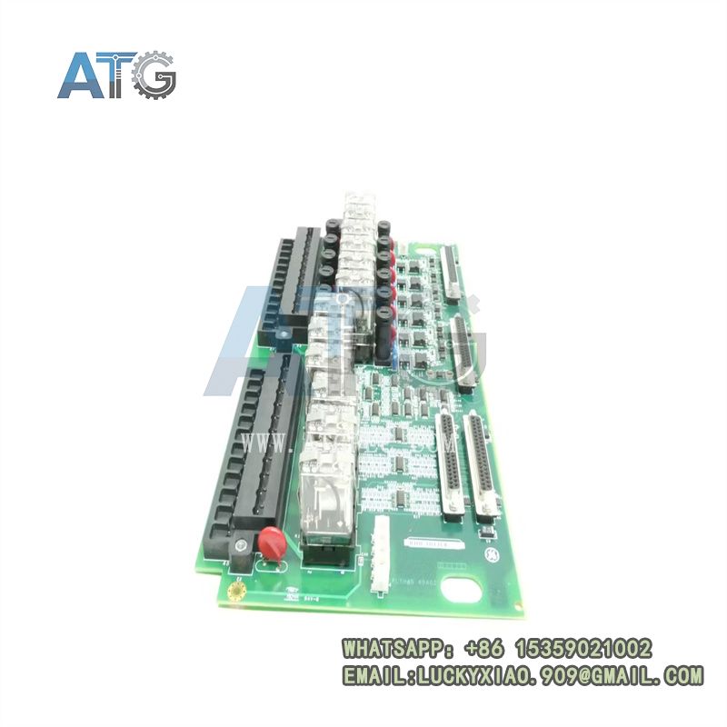
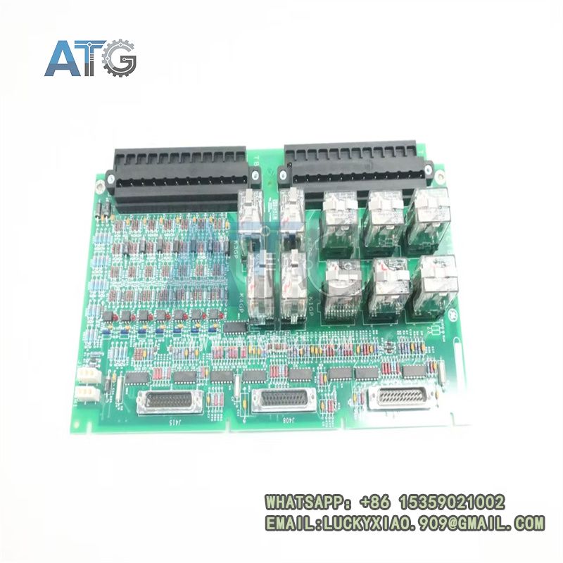

Description
Product Overview
The GE IS200ECTBG1ADE is an Exciter Contact Terminal Board (ECTB) from the GE EX2100 generator excitation control system. It sits between the excitation control electronics and the field contactor, breaker and lockout circuits, acting as the discrete wiring interface for the entire excitation package.
This is a passive and relay-level board. It does no signal processing. Its job is to bring field contact inputs onto terminals, switch relay outputs, and route the signals through to the EMIO interface board that talks to the controller. The G1 variant is designed exclusively for redundant excitation control, where three controller channels vote on every contact action.
Field wiring lands on screw-terminal blocks along the board edge. Internal relays and opto-isolated input circuits handle the switching and sensing. Three 25-pin D-sub connectors carry signals to and from the EMIO board, which in turn interfaces with the M1, M2 and C redundant controllers.
The ADE suffix marks a specific production revision within the G1 family. It is the board you will find on most modern redundant EX2100e excitation retrofits.
Core Product Features
- Six auxiliary contact inputs, wet at 70 VDC from the M1/M2 control supplies, read breaker auxiliaries, contactor status and interlock contacts from the field.
- Four general-purpose Form-C relay outputs switch status and control signals to external annunciators, indicators and auxiliary circuits.
- Two dedicated trip contact outputs drive customer lockout relays and field trip circuits, the hardwired last line of defense.
- Three 25-pin D-sub connectors fan signals out to the EMIO board, which serves all three redundant controller channels (M1, M2, C).
- Redundant-mode hardware design: the board is wired for 2oo3 voting and will not operate correctly in a simplex rack.
- Screw-terminal field wiring on the board edge simplifies marshalling and eliminates custom cable harnesses.
- On-board relay status LEDs give a visual indication of output state during walkdowns and commissioning.
- The board mounts in the exciter cabinet on a standard rack slot, with the D-sub connectors facing the controller backplane.
Technical Specifications
| Item | Specification |
|---|---|
| Ordering model | IS200ECTBG1ADE |
| Product type | Exciter contact terminal board (ECTB) |
| Compatible system | GE EX2100 / EX2100e excitation control |
| Operating mode | Redundant control only (G1 family) |
| Auxiliary contact inputs | 6 channels, 70 VDC wetting, M1/M2 supplied |
| General-purpose relay outputs | 4 × Form-C contacts |
| Trip contact outputs | 2 channels, customer lockout drive |
| Controller interface | 3 × 25-pin D-sub to EMIO board (M1, M2, C) |
| Field termination | Screw-terminal blocks on board edge |
| Status indicators | Relay and channel LEDs |
| Mounting | Exciter cabinet rack slot |
| Humidity | 5% – 95% RH, non-condensing |
| PCB coating | Conformal coated |
| Origin | United States |
| Certifications | CE, UL, industrial EMC |
The G1 board is purpose-built for redundant EX2100 packages. If your exciter runs in simplex mode, the correct part is the ECTBG2 variant, not this one. Swapping a G1 into a simplex rack leaves the third D-sub connector unused and misconfigures the voting logic.
Product Details and Application Fields
Product Details
Redundant vs simplex split. GE makes two ECTB variants for EX2100. G1 is for redundant 2oo3 packages, G2 is for simplex. They look similar and share the slot, but the internal wiring and D-sub connector mapping differ. Ordering the wrong one is a common spare mistake.
Signal flow on the input side. Field contact closures come in on screw terminals, pass through opto-isolation, and exit on the D-sub connectors to the EMIO board. The 70 VDC wetting voltage is supplied by the M1/M2 control rails, so a dead wetting supply shows up as all inputs open.
Signal flow on the output side. Relay commands come back from the EMIO board over the D-sub, drive on-board relays, and the relay contacts close on the screw terminals to operate external devices. The Form-C contacts are dry, so the customer supplies the switched voltage.
Trip outputs. The two trip contact outputs are rated for customer lockout relays. They are hardwired and do not depend on the controller being alive. This is the path that fires when the excitation system needs an immediate field trip.
EMIO pairing. The ECTB board never talks directly to the controller CPU. All signals pass through the EMIO (Exciter Module I/O) board, which handles the redundant channel arbitration. If a D-sub cable works loose, the symptom is a missing channel, not a dead whole board.
Revision context. ADE is a late G1 revision. Earlier ADA and AAA variants share the slot but differ in jumper settings and relay ratings. Photograph the original board’s jumpers before pulling it, because factory defaults do not match a tuned excitation system.
Application Fields
- Generator field breaker and contactor status monitoring in redundant EX2100e excitation packages
- Field trip and lockout relay driving for large steam and gas turbine generators
- Excitation system annunciator and alarm relay outputs in power plant control rooms
- 2oo3 redundant excitation control on nuclear and utility-grade turbine generators
- De-excitation and crowbar status contact termination in EX2100 cabinets
- Retrofit of legacy EX2000 excitation systems to the Mark VIe-based EX2100e platform
- Industrial cogeneration and captive power plant excitation contact interfacing
Related Model Recommendations
- IS200ECTBG2A — simplex-mode exciter contact terminal board, for non-redundant EX2100 installations where G1 hardware is overkill.
- IS200ECTBG1ADA — earlier G1 redundant revision with the same slot and function, used as a direct spare on legacy cabinets.
- IS200EMIO — Exciter Module I/O board that pairs with the ECTB, carrying all three redundant controller channels over D-sub cables.
- IS200EXHSG3REC — high-speed relay driver board that drives the DC field contactors, working alongside the ECTB in the same exciter cabinet.