
Description
1440-DYN02-01RJ Allen-Bradley Product Introduction
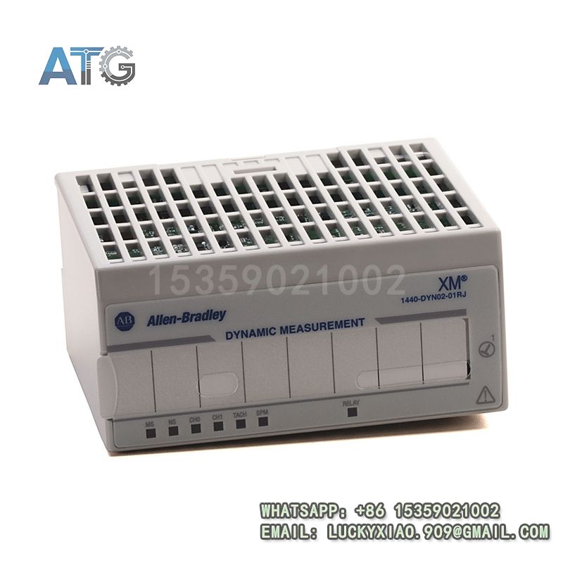
- Model: 1440-DYN02-01RJ
- Brand: Allen-Bradley (Rockwell Automation)
- Series: Allen-Bradley 1440 XM Dynamic Measurement Series
- Core Function: Rotating equipment vibration and speed monitoring
- Type: Condition Monitoring Module
- Key Specs: 24VDC, 2 dynamic channels, ControlNet
- Supply Status: In Stock
- Stock: 1
- Warranty: 1 year
- Ship From: China
1440-DYN02-01RJ
Product System Function Introduction
The 1440-DYN02-01RJ is a high-precision condition monitoring module under Allen-Bradley’s 1440 XM Series, specially designed for real-time monitoring of vibration, pressure, deformation and speed of rotating equipment in industrial automation systems. It is designed to integrate with ControlLogix controllers through the 1440-ACNR ControlNet adapter, providing reliable data support for predictive maintenance and equipment fault diagnosis. Its specific system functions are divided into the following points:
1. Functional Positioning and Core Value: As a standard dynamic measurement module of the 1440 XM Series, this module is positioned as a professional condition monitoring unit, responsible for collecting and processing dynamic signals of rotating equipment, including vibration, speed and other key parameters. Its core value lies in realizing real-time and accurate monitoring of equipment operating status, early warning of potential faults, reducing unplanned downtime, and ensuring the safe and stable operation of industrial equipment, which is widely used in predictive maintenance scenarios[3].
2. Monitoring Performance and Signal Processing: The module is equipped with 2 dynamic input channels and 1 tachometer channel, which can connect with common vibration sensors (such as eddy current probes, accelerometers) and voltage output sensors to collect real-time equipment data[3]. It supports both synchronous and asynchronous measurement, and adopts a signal processing method that performs two-stage integration and FFT processing with up to 30 measured parameters, ensuring the accuracy and comprehensiveness of monitoring data. It can measure speed up to 1.2 M rpm with a pulse rate of 1-50,000 events per revolution, meeting the monitoring needs of high-speed rotating equipment.
3. Compatibility and System Integration: It is specially designed to work with the 1440-ACNR ControlNet adapter, realizing data transmission and communication with the ControlLogix controller through the ControlNet network[2]. It can be seamlessly integrated into the industrial automation system, and its I/O and configuration tables can be exposed as common tags in the Allen-Bradley Studio 5000 Logix Designer software, facilitating parameter configuration and data monitoring. A single ControlNet adapter can support up to 10 1440-DYN02-01RJ modules, which is convenient for system expansion and distributed monitoring[2].
4. Practicality and Fault Diagnosis: The module is equipped with a built-in virtual relay and complete fault diagnosis function, which can timely detect sensor faults, signal abnormalities and module malfunctions, and send alarm signals to the controller and HMI equipment, facilitating maintenance personnel to quickly locate and handle faults. It adopts a modular design, which is small in size and easy to install on the 1440-TBS-J spring clamp terminal base, adapting to different on-site installation environments. It can work stably in the temperature range of -20℃ to 70℃, with strong environmental adaptability.
Application Industries
With its high monitoring precision, strong compatibility and reliable performance, the 1440-DYN02-01RJ condition monitoring module is widely used in industrial fields that require real-time monitoring of rotating equipment, mainly covering the following fields:
1. Petrochemical Industry: Applied in rotating equipment such as pumps, fans and turbines in chemical production workshops and pipeline systems, it monitors vibration, speed and pressure parameters in real time, early warns of equipment faults, and ensures the safety and stability of the production process, adapting to the harsh on-site environment of the petrochemical industry.
2. Power Generation Industry: Used in thermal power plants, hydropower plants and other power generation equipment (such as generators, steam turbines), it monitors the vibration and speed of key rotating components, realizes predictive maintenance, reduces equipment failure rate, and ensures the stable operation of the power generation system.
3. Automotive Manufacturing Industry: Applied in rotating equipment such as motors, gearboxes and conveyor rollers in automobile assembly lines and parts processing workshops, it monitors equipment operating status in real time, ensures the coordinated operation of the production line, and improves production efficiency and equipment service life.
4. Heavy Machinery Industry: Used in rotating components of heavy machinery such as excavators, cranes and rolling mills, it monitors vibration and deformation parameters, avoids equipment damage caused by excessive vibration, and reduces maintenance costs and downtime.
5. Water Treatment Industry: Applied in rotating equipment such as water pumps and blowers in sewage treatment plants and water supply systems, it monitors equipment operating status in real time, ensures the smooth operation of the water treatment process, and guarantees water supply and drainage stability.
Usage Instructions
To ensure the long-term stable operation of the 1440-DYN02-01RJ condition monitoring module and the accuracy of equipment monitoring data, the following usage instructions should be followed:
1. Installation Requirements: Install the module on the specified 1440-TBS-J terminal base, ensure firm installation and good contact to avoid poor contact caused by vibration. Install it in a dry, well-ventilated position, avoiding direct sunlight, high temperature (above 70℃) and areas with strong vibration or heavy dust. Keep a certain distance from high-voltage components to avoid electromagnetic interference, and ensure good ventilation around the module to prevent overheating.
2. Wiring Specifications: The module adopts 24VDC power supply. When connecting the power supply, strictly distinguish the positive and negative poles, and never reverse the connection to avoid short circuit burning the internal components. For sensor wiring, use standard signal cables to connect the dynamic input channels and tachometer channel with the corresponding sensors, ensure the wiring is firm and the contact is good, and the shielding layer of the cable should be properly grounded to reduce signal interference. For communication wiring, connect it to the 1440-ACNR ControlNet adapter according to the specifications, and ensure the communication line is intact. It is strictly prohibited to wire with power on to avoid electrical shock or module damage.
3. Parameter Configuration and Debugging: Use Allen-Bradley Studio 5000 Logix Designer software to configure the module parameters, including sensor parameters, monitoring thresholds, signal processing modes and communication parameters. After the configuration is completed, download the parameters to the module through the ControlNet adapter and restart the module to make the configuration take effect. During debugging, check the signal collection status, ensure that the monitoring data is accurate, and adjust the monitoring thresholds in time according to the actual equipment operation status.
4. Operation and Maintenance: During daily operation, regularly check the running status of the module (such as power indicator, signal indicator), and monitor the monitoring data through Studio 5000 software or FactoryTalk View HMI software to ensure that the module is running normally. Regularly check the wiring for looseness, clean the surface of the module to remove dust and stains, and check the connection status of the sensor. Regularly back up the module configuration parameters to a computer or storage device to prevent parameter loss due to unexpected power failure or module failure. When a fault occurs, use the fault diagnosis function of the software to locate the fault, and contact professional maintenance personnel for inspection and replacement if necessary.
5. Safety Precautions: Cut off the power supply of the entire system before installation, disassembly or wiring to prevent electrical shock or module damage. Do not touch the module pins, terminals or internal components with wet hands or metal tools to avoid short circuit. Avoid collision or impact on the module to prevent physical damage to the enclosure and internal components. In flammable and explosive industrial environments, strictly follow the on-site safety regulations and ensure that the module is used in a safe environment to prevent safety accidents. Regularly calibrate the sensor and module to ensure the accuracy of monitoring data.