
Description
1756-RM2 Allen-Bradley Product Introduction
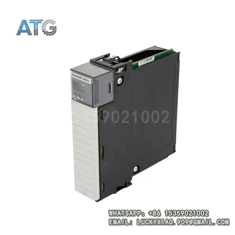
- Model: 1756-RM2
- Brand: Allen-Bradley (Rockwell Automation)
- Series: Allen-Bradley 1756 ControlLogix PLC Series
- Core Function: CPU redundancy control and fault switching
- Type: Redundancy Module
- Key Specs: 24VDC, Redundant switching, ControlLogix compatible
- Supply Status: In Stock
- Stock: 5
- Warranty: 1 year
- Ship From: China
1756-RM2
1756-RM2 Product System Function Introduction
The 1756-RM2 is a high-reliability redundancy module under Allen-Bradley’s 1756 ControlLogix Series, specially designed to realize redundant control of ControlLogix CPU modules, ensuring uninterrupted operation of industrial automation systems when a single CPU fails. It integrates fast fault detection, seamless switching and real-time data synchronization functions, supporting seamless integration with 1756 series CPUs and chassis, and is widely used in industrial scenarios requiring high system availability and fault tolerance. Its specific system functions are divided into the following points:
1. Functional Positioning and Core Value: As a dedicated redundancy module of the 1756 ControlLogix Series, this product is positioned as a key protection component in high-reliability industrial control systems, responsible for monitoring the operation status of dual CPUs, realizing real-time data synchronization and seamless switching between master and standby CPUs. Its core value lies in eliminating single points of failure, ensuring continuous operation of the system, reducing unplanned downtime, and protecting the safety and stability of industrial production processes.
2. Redundancy Performance and Switching Advantage: The module supports dual-CPU redundant configuration (master-standby mode), which can real-time monitor the running status of the master CPU (such as operation status, communication status, fault information). When the master CPU fails, it can complete the switching to the standby CPU within milliseconds, realizing zero downtime switching without affecting the normal operation of the system. It adopts high-speed data synchronization technology to ensure that the master and standby CPUs maintain consistent program, configuration parameters and real-time data, avoiding data loss or inconsistency during switching.
3. Compatibility and System Integration: It is fully compatible with Allen-Bradley 1756 ControlLogix chassis and 1756 series CPUs (such as 1756-L71, 1756-L72), and can be directly installed in the 1756 chassis without additional modification to the system. It supports seamless integration with Allen-Bradley Studio 5000 Logix Designer software, facilitating redundant configuration, status monitoring and fault diagnosis. The module communicates with the CPU through the backplane of the chassis, ensuring stable and reliable data transmission and avoiding external interference.
4. Reliability and Fault Diagnosis: The module adopts a ruggedized industrial design, with strong anti-interference, dust-proof and anti-vibration performance, which can adapt to harsh industrial on-site environments with high temperature (-20℃ to 65℃), high humidity and strong electromagnetic interference. It is equipped with a complete fault self-diagnosis function, which can timely detect module faults, communication abnormalities and CPU redundancy faults, and send alarm signals through indicator lights and software, facilitating maintenance personnel to quickly locate and handle faults. The low-power design ensures long-term stable operation, reducing the overall operation and maintenance cost of the system.
Application Industries
With its high reliability, fast switching speed, strong compatibility and excellent fault tolerance, the 1756-RM2 redundancy module is widely used in industrial automation projects that require high system availability and uninterrupted operation, mainly covering the following fields (combining Allen-Bradley’s strength industries):
1. Petrochemical Industry: Applied in chemical production workshops, pipeline control systems and storage tank monitoring systems, it realizes redundant control of the core control system, ensuring that the production process is not interrupted due to CPU failure, and adapting to the harsh on-site environment and high-safety requirements of the petrochemical industry.
2. Power Generation Industry: Used in thermal power plants, hydropower plants and other power generation systems, it provides redundant protection for the control system of generators, turbines and other key equipment, ensuring the stable operation of the power generation system and the safe transmission of electric energy, avoiding economic losses caused by system downtime.
3. Rail Transit Industry: Applied in rail transit signal control systems, power supply systems and vehicle control systems, it realizes redundant control of the core CPU, ensuring the safe and stable operation of rail transit, adapting to the high-reliability and high-safety requirements of the rail transit field.
4. Water Treatment Industry: Used in water supply and drainage systems, sewage treatment plants and water quality monitoring stations, it provides redundant protection for the control system, ensuring the continuous operation of water treatment equipment, avoiding water supply and drainage interruption or sewage treatment failure caused by system faults.
5. Automotive Manufacturing Industry: Applied in automobile assembly lines and key parts processing workshops, it realizes redundant control of the production line control system, ensuring the continuous operation of the production line, improving production efficiency and reducing losses caused by unplanned downtime.
1756-RM2 Usage Instructions
To ensure the long-term stable operation of the 1756-RM2 redundancy module and the safe and reliable operation of the entire redundant control system, the following usage instructions should be followed:
1. Installation Requirements: Install the module into the 1756 ControlLogix chassis, ensure firm connection with the backplane, and check that the positioning pin is aligned to avoid poor contact. Install the chassis in a dry, well-ventilated control cabinet, avoiding direct sunlight, high temperature (above 65℃) and areas with strong vibration or heavy dust. Keep a certain distance from high-voltage components to avoid electromagnetic interference, and ensure good ventilation around the module to prevent overheating. Ensure that the dual CPUs and redundancy module are installed in the specified slots of the chassis.
2. Wiring Specifications: The module adopts 24VDC power supply, which is powered by the chassis power supply, without additional independent power wiring. Ensure that the chassis power supply is stable and the wiring is firm, avoiding poor contact or power failure. The module communicates with the CPU through the chassis backplane, so no additional communication wiring is required. It is strictly prohibited to install or disassemble the module with power on to avoid electrical shock or module damage.
3. Parameter Configuration and Debugging: Use Allen-Bradley Studio 5000 Logix Designer software to configure the redundant parameters, including master-standby CPU setting, switching delay, fault alarm threshold and data synchronization parameters. After the configuration is completed, download the parameters to the system, and restart the chassis to make the redundant configuration take effect. During debugging, simulate CPU faults to test the switching performance, ensure that the switching is smooth and fast, and check the data synchronization status to avoid data inconsistency.
4. Operation and Maintenance: During daily operation, regularly check the running status of the module (such as power indicator, redundancy status indicator), and monitor the redundant system status through Studio 5000 software to ensure that the master and standby CPUs are running normally and the module is working stably. Regularly check the chassis backplane connection, clean the surface of the module to remove dust and stains, and check the power supply status of the chassis. Regularly back up the system configuration parameters to a computer or storage device to prevent parameter loss due to unexpected faults. When a fault occurs, use the fault diagnosis function of the software to locate the fault, and contact professional maintenance personnel for inspection and replacement if necessary.
5. Safety Precautions: Cut off the power supply of the entire system before installation, disassembly or maintenance to prevent electrical shock or module damage. Do not touch the module pins, terminals or internal components with wet hands or metal tools to avoid short circuit. Avoid collision or impact on the module to prevent physical damage to the enclosure and internal components. In flammable and explosive industrial environments, strictly follow the on-site safety regulations and ensure that the module is used in a safe environment to prevent safety accidents. Regularly check the redundant system status and deal with faults in a timely manner to avoid system downtime.